
In motion control systems, gears are used to change the torque and speed delivered by a motor to a driven component. Depending on how the gears are arranged, they can either increase the delivered torque and decrease the output speed (the most common arrangement in motion control applications) or decrease the delivered torque and increase the output speed. Gears can also help to improve the load-to-motor inertia ratio by reducing the amount of load inertia reflected to the motor. This allows the motor to better control the load and improves characteristics of system performance such as settling time.
The relationship between the input speed to the gearbox and the output speed delivered to the driven load is commonly referred to as the gear ratio. One of the simplest ways to determine the gear ratio is to take the ratio of driven gear teeth to driving gear teeth
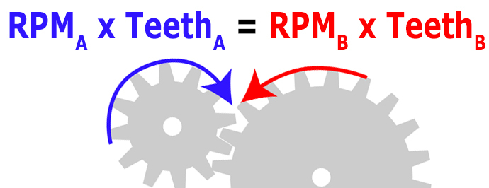
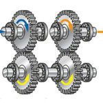
Image credit: Precision Microdrives
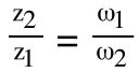
z1 = number of teeth on driving gear
z2 = number of teeth on driven gear
ω1 = speed of driving gear
ω2 = speed of driven gear
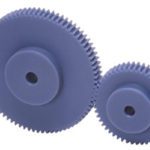
To achieve torque multiplication and speed reduction, the driving gear (also referred to as the pinion) will be smaller than the driven gear (typically referred to as simply the “gear” or “wheel”).
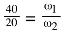
This is easy to imagine if you picture a driving gear (pinion) with 20 teeth and a driven gear with 40 teeth. For every one revolution of the driving (20-tooth) gear, the driven (40-tooth) gear will only complete ½ revolution. In other words, the smaller, driving gear will turn twice for every one revolution of the larger, driven gear.

![]()
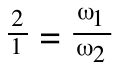
This configuration gives us a gear ratio of 2:1, which means that the speed from the motor is reduced by a factor of 2 and the torque from the motor is multiplied by a factor of 2 (not accounting for any losses due to inefficiencies in the gear train).
For multi-stage gearing, the gear ratio between the output and the input is simply the product of all the intermediate gear ratios. For example, if a three-stage gearbox consists of a first stage with a 10:1 gear ratio, a second stage of 5:1, and a third stage of 3:1, the total transmission ratio will be 150:1.
Expressions of gear ratio are typically factored down so that the denominator (representing the number of teeth on the driving pinion) is expressed as “1,” even if that means the numerator (representing the number of teeth on the driven gear) would result in a decimal. For example, if a driven pinion has 21 teeth (z2 = 21) and a driving pinion has 9 teeth (z1 = 9), instead of 21:9 or 7:3, this gear ratio will typically be expressed as 2.3:1.
Per the ISO 701:1998 standard, gear ratio is denoted with the letter “u” and total transmission ratio — the total ratio of input speed to output speed — is denoted with the letter “i.” In this notation, the denominator of the ratio is set to 1, and only the numerator is expressed. So an 11:1 ratio would be expressed as i=11, and a 2.3:1 ratio would be expressed as i=2.3.
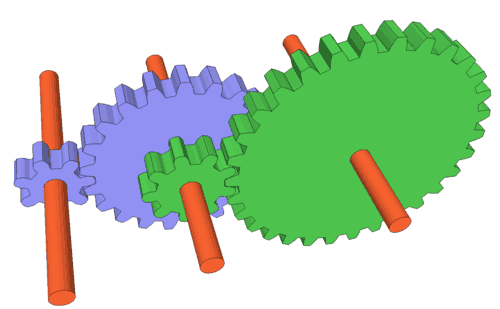
Image credit: Woodgears
Transmission ratio calculation: Special cases for planetary and worm gears
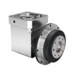
The calculation of transmission ratio for a single-stage planetary gearbox depends on which gears are the driven, stationary, and output components. In motion control applications, planetary gears typically have a driven sun gear, a stationary ring gear, and a carrier that drives the output shaft. For this configuration, the total transmission ratio (ip) is equal to one plus the ratio of ring gear teeth (zr) to sun gear teeth (zs), or ip = 1 + zr/zs.
For worm gears, the gear ratio equals the number of teeth on the gear divided by the number of starts on the worm.


Leave a Reply
You must be logged in to post a comment.